Inglenook Sidings
Inglenook Sidings is a train switching puzzle invented by Alan Wright of
England in 1978. The idea is to arrange train cars in a prescribed
order. The task is moderately difficult because of the limited track
lengths.
This project combined my interest in electronics and computers with
model railroading. Its main feature is an automatic mode that operates
the engine and turnouts to reverse a sequence of train cars. An
unintentional feature was perhaps an answer to the question of why
serious modelers avoid automatic uncoupling. It's difficult to get it to
work reliably, especially in N-scale.
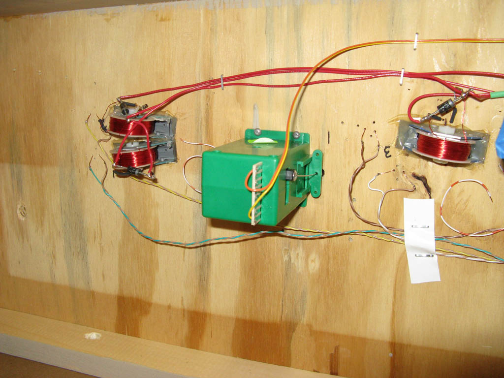
To improve reliability electromagnets were used for the uncouplers
instead of the more common permanent magnets, which can uncouple cars
when not intended.
The Kadee 708 electromagnets are designed for HOn3 and fit N-gauge
track. I modified the suggested assembly by insulating the field plates
from each other to prevent electrical shorts. I also eliminated the
bulky mounting plates by simply hot-gluing the electromagnets into the
layout. This is explained below.
To prevent the engine from stalling at slow speeds Peco turnouts with
electrofrogs were used. They are actuated by Tortoise servos, which are
quieter and more realistic than solenoids.
To further reduce the possibility of stalls, the steam engine has
additional electrical pickup in its tender.
Cars with the most reliable Micro-Trains couplers were selected. Each
car has a super (neodymium) magnet mounted under it that activates reed
switches hidden in the track. These detect when a car is positioned over
an uncoupler or has cleared a turnout. Many different kinds of magnets
were tried before suitable ones were found.
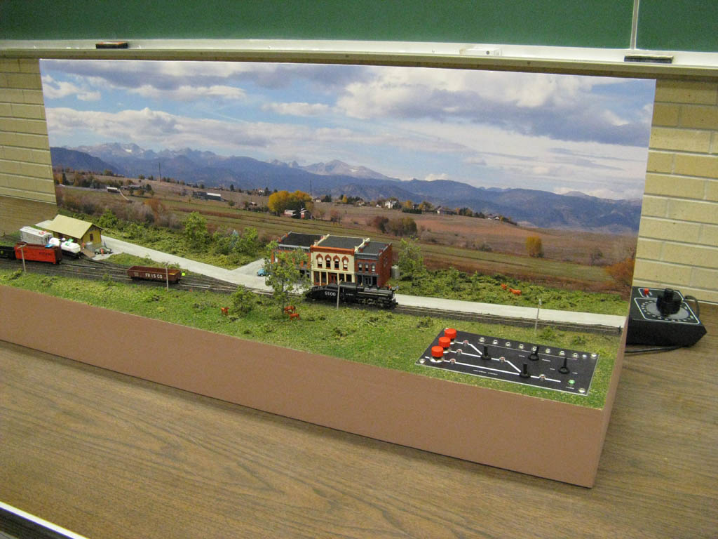
The backdrop is a photograph taken with an 8-megapixel (Canon A720)
camera east of Boulder Colorado. Mike's Camera made the print for
$38.
The layout is designed to operate the standard 3-3-5-3 puzzle, but a
scaled-down 2-2-3-2 version has proven to be more suitable for train
shows where visitors have only a limited amount of time to watch.
Electromagnetic Uncouplers for N-Scale
Electromagnets were chosen instead of the more common permanent magnets
because the latter can accidentally uncouple cars when not intended. An
electromagnet, of course, is only energized when you want to uncouple
cars.
The couplers are the Magne-Matic kind like used on Micro-Trains cars, not
the Rapido kind used on less expensive equipment. The Kadee 708 uncoupler
is designed for HOn3, which fits N-gauge track.
The main problem with Kadee's installation is that it's likely to cause
a short circuit. Another problem is the bulky mounting plates. These
prevent mounting uncouplers side-by-side on closely spaced sidings, and
they're difficult to conceal.
 As you can see in
the diagram there's very little space (if any) between the field plates
on the uncoupler and wheel flanges. The metal wheels on an engine will
likely touch both the rails and the field plates simultaneously; and
since the plates are electrically connected, this shorts out the track.
One solution (which is extensively explained on the Internet)
is to increase the space between the plates and the rails by bending the
plates, but that's difficult to do accurately, and it also requires that
all couplers be readjusted. I chose instead to insulate the field plates
from each other. Here's how:
As you can see in
the diagram there's very little space (if any) between the field plates
on the uncoupler and wheel flanges. The metal wheels on an engine will
likely touch both the rails and the field plates simultaneously; and
since the plates are electrically connected, this shorts out the track.
One solution (which is extensively explained on the Internet)
is to increase the space between the plates and the rails by bending the
plates, but that's difficult to do accurately, and it also requires that
all couplers be readjusted. I chose instead to insulate the field plates
from each other. Here's how:
Make a pair of paper washers from a 3x5 index card. Draw two circles on
the card using the uncoupler's cylindrical core as a template. Cut the
circles out slightly larger than the core. Punch holes in the centers
with a standard 1/4" paper punch. Replace the metal bolt and nut that
comes with the uncoupler with a nylon bolt and nut (a 10/24 3/4"
available from McGuckin Hardware).
To reduce the possibility of the wheel flanges riding up over the field
plates, file a 1/8" bevel on the rail-side on both ends of each plate.
 Assemble the uncoupler. Insert the nylon bolt into one of the (correctly
oriented) field plates. Add in order: the paper washer, the cylindrical
core, the coil, and the plastic field plate divider. Rotate the coil so
that its notch engages with the plate divider. Add the second paper
washer and field plate. Note that the nylon nut has a built-in washer on
one side. Loosely screw that side on so that it's in contact with the
field plate. Gently tap the field plates on a flat surface to make sure
they are exactly parallel, and then tighten the nut.
Assemble the uncoupler. Insert the nylon bolt into one of the (correctly
oriented) field plates. Add in order: the paper washer, the cylindrical
core, the coil, and the plastic field plate divider. Rotate the coil so
that its notch engages with the plate divider. Add the second paper
washer and field plate. Note that the nylon nut has a built-in washer on
one side. Loosely screw that side on so that it's in contact with the
field plate. Gently tap the field plates on a flat surface to make sure
they are exactly parallel, and then tighten the nut.
Burn the lacquer coating off about 1/2" of the wire leads with a match or
lighter. Use fine sandpaper to remove most of the remaining residue.
Mounting
Since both the upper and lower mounting plates are bulky it's desirable
to get rid of them, and as it turns out this is easy to do.
Instead of cutting a 2-7/8 x 1-1/16 hole in your layout like Kadee
specifies, cut a smaller hole, just large enough to insert the uncoupler
from the underside, about 2-1/8 x 3/4".
Cut away 2-1/8" of ties from the center of the track to allow the field
plates to be inserted between the rails. Save any tie pieces that fall
away so they can be glued on later.
Make a gasket from an index card with a 2 x 3/8" hole that passes the
field plates but covers the hole in the layout, and glue it on the
layout.
Insert the assembled uncoupler through the underside of the cutout in the
layout. Hold it in place while inserting (N-scale 4x8 bass wood) shims to
center it between the rails. Cover the uncoupler with masking tape to
hold the shims in place. Place a wooden block over the uncoupler, and use
it to position the field plates at the same level as the rails.
With the infinite dexterity of a model railroader, from the underside of
the layout, apply two dabs of hot glue on opposite corners of the
uncoupler to temporarily hold it in place. Closely check the alignment.
If it's wrong, a hair dryer can be used to loosen the glue enough to
reposition it. When it's correctly aligned, apply more hot glue to hold
it permanently.
Operation
Kadee recommends running the uncoupler at 12 volts DC. You can probably
get by with a 12 volt, 1 amp (1000 mA) DC wall-wart from Radio Shack,
although more than 1 amp would be better. You might also get by with
using the 18-volt AC accessory power that's typically available on a
power-pack. (The DC power supply I used was made from miscellaneous
parts.)
The uncoupler coil is 8.5 ohms, which means that will try to draw more
than an amp (at 12V), and it will get hot if left on for more than a few
seconds at a time. Use a momentary push button rated for 2 amps or
more.

Links
In manual mode the layout is operated as a switching puzzle. Here are
the rules.
Here is a nice Java script that lets you operate the puzzle directly
from your browser:
http://www.precisionlabels.com/shunt/jpage330.html
The magnets that are mounted on the bottom of each train car and are
used to activate the reed switches in the track came from here.
They are the smallest ones at the top of the page.
This is the reed switch. The small size makes them easier to conceal.
You can buy them here.
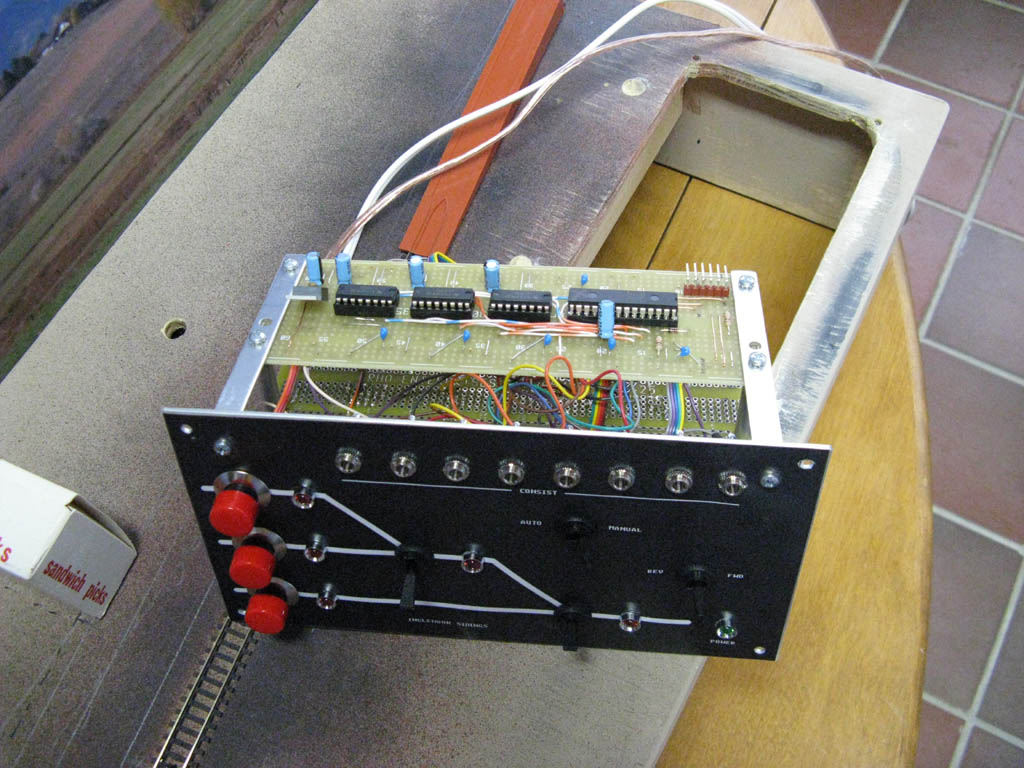
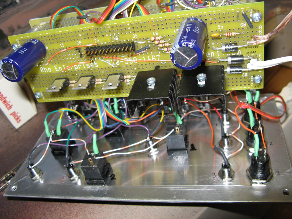
Here is a schematic diagram of the circuitry mounted on the underside of
the control panel: Schematic.
The heart of the control system is the
PIC24FJ64GA002 from Microchip.
Here is the code that runs in the PIC: Inglenook.C
-Loren Blaney
Last updated 28-May-2026