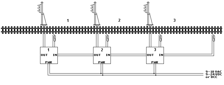
The controller circuit board is designed to use a magnetic reed switch to detect the presence of trains. There are two versions: prototypical and timer. Prototypical operation requires several boards to be interconnected so they can display red, yellow, and green lights (or aspects, such as with Pennsy positional signals) trailing behind trains as they travel from block to block. The timer version is simpler. It operates a single signal independent of any others. Red is displayed when a train passes, after a few seconds yellow is displayed, and after a few more seconds the signal turns back to green.
Cables connect the board to a reed switch and power source. A third cable is required for prototypical operation that chains boards together. If the boards are not connected in a complete loop then an extra reed switch is needed to terminate each chain of signals. Note that the last board, shown on the right, is connected to the reed switch at its INPUT socket.
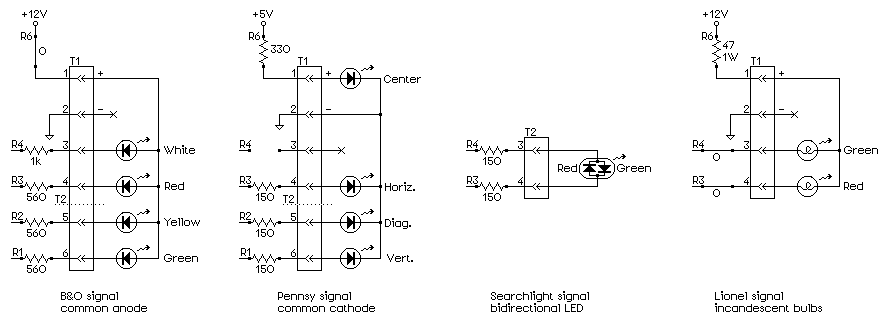
1. The first thing to determine is how your signal will be connected to the circuit board: with a miniature plug or with screw terminals?
The advantage of the miniature plug is that it makes it easy to attach the signal to the circuit board mounted under the layout. The six-pin plug requires a 5/16" hole in the layout (that can be later covered with scenery and held with hot glue). If your signal does not have a yellow light (aspect) then you can probably get by with a four-pin plug that passes through a 1/4" hole. Resistors attached to the leads of the signal are clipped off and mounted on the circuit board. Values can be substituted to adjust brightness. One pin of the plug is removed and the corresponding hole in the socket is obstructed to "key" the connector, thus preventing it from being plugged in wrong. Soldering wires onto the miniature (2 mm spacing) plug is the most difficult step of assembling this kit.
On the other hand, most commercial boards use screw terminals, and that's an option here. The advantage is that individual wires on the signal can be passed through an even smaller hole, and any resistors can be left attached to the wires. The disadvantage is that sometimes it's difficult to connect the individual wires to the correct terminals under the layout.
2. How many connections are needed: six, four, or two? If there is no yellow light (aspect) then a four-pin plug or four-screw terminal is sufficient. If the signal has a bidirectional red/green LED with only two leads then a two-screw terminal is sufficient. (A four-pin plug is still used in this last case because it prevents plugging in backwards.)
3. Which voltage will your signals use: rectified input or regulated five volts? This determines the position of the resistor R6. In many cases R6 is just a (0 ohm) jumper wire that connects the rectified input voltage. Common cathode LEDs (such as on Pennsy positional signals) must use the regulated five volts, so R6 is installed in that position. Incandescent bulbs use the rectified input voltage. If they were originally powered from an AC source then R6 has a value that compensates for the voltage increase due to rectification (typically 47 ohms for 12 VAC).
4. An LED must always have a resistor connected in series. Will this resistor be mounted on the board or is it attached to the signal? If the resistor is on the board, what value is it? If you know the voltage your signal runs from (typically 12 VDC) then a brightness adjustment tool (a rheostat, which will be provided at the clinic) can be used to determine this value.
If you have any doubts about the configuration needed for your signal, have it verified by Loren Blaney.
Your block signal
Soldering iron with small tip, holder, and sponge
Needle-nose pliers
Wire nipper (Xuron track cutter works well)
Wire stripper (for 24 gauge cables and possibly signal leads)
Bright light (for close-up soldering)
Eye protection (for close-up soldering, which can sometimes spatter)
Extension cord
Power outlet strip
Tweezers
Small screwdriver (for screw terminal, if used)
Small container for trash
Phillips screwdriver #4 (for mounting circuit board on layout)
Any kind of tape (to hold sockets straight while soldering)
Volt-ohm meter
Heat gun or cigarette lighter (for heat-shrink tubing)
Hot glue gun
"Helping hands" (to hold parts while soldering)
Opti-visor (to inspect solder joints)
Quan. Item  Description                                     Supplier/Part no.
----- ----  -----------                                     -----------------
 1          Printed circuit board                           Advanced Circuits
 1    D1    Bridge rectifier, DF04M, 1A, DIP                Jameco 102971
 1   (IC1)  Socket, IC, 14-pin DIP                          Jameco 112214
 1 c (IC2)  Socket, IC, 16-pin DIP                          Jameco 112222

 1    C3    Capacitor, 0.1uF radial ceramic, "104"          Jameco 544868
 1    R7    Resistor, 10k ohm 1/4 W                         Jameco 691104
 1 p  R5    Resistor, 560 ohm 1/4 W                         Jameco 690806
 4 +  R1-R4 Resistors, 1/4 W, determine LED brightness      Jameco 10664
 1 +  R6    Resistor, 1 W or jumper wire (see text)         JB Saunders

 1 t  SW1   Rotary DIP Switch, 16 position                  Jameco 139652

 1 +  S4    Socket, 2 mm six-hole                           JB Saunders
 2    S1    Sockets, 0.100" two-hole (REED)                 Digi-Key S7000-ND
 2 p  S2,S3 Sockets, 0.100" three-hole (INPUT/OUTPUT)       Digi-Key S7001-ND
 2    P1    Headers, 0.100" two-pin  (9-18 VAC)             Digi-Key WM6002-ND
 1 +  T1    Terminal block, 4 screws                        Jameco 2124411
 1 +  T2    Terminal block, 2 screws                        Jameco 2094506

 1 +  C4    Capacitor, 6.8uF 35V tantalum dipped            Jameco 33873
 1    C2    Capacitor, 22uF 16V radial                      Jameco 1946295
 1    C1    Capacitor, 470uF 35V radial                     Jameco 93817

 1    IC3   LM7805AC, 5V regulator, 1.5A                    Jameco 924570
 1    IC1   PIC16F684-I/P, microcontroller, programmed      Jameco 312590
 1 c  IC2   ULN2003, Darlington driver, DIP-16              Jameco 34278

 5          Feet wire, 24 gauge, two-conductor, stranded    Jameco 100299
15 p        Feet wire, 24 gauge, two-conductor, stranded    Jameco 100299
 2 p  P2,P3 Headers, 0.100" three-pin                       Digi-Key WM6003-ND
 1          Magnetic reed switch                            Digi-Key HE503-ND
 1          3/16" heat-shrink tube, 1-1/4" long, clear      JB Saunders

 4          Wood screws, #4 1/2" Phillips                   McGuckin Hardware
 4          Spacers, mounting, 5/32" #4                     JB Saunders sold out
 8          Rare earth magnets, rod 1/8x1/8"                Magcraft.com NSN0658
 1/2        Foot jumper wire, bare copper
 2          Feet solder, rosen-core
 1          These assembly directions

   t timer version
   p proto version
   c unused by common cathode and bidirectional red/green LEDs
   + option
The parts list is in the recommended order of assembly, which is basically to solder on the shorter parts first.
NOTE: Components are inserted on the side of the board with the most metal, which might be opposite of what you expect. The solder side is labeled SOLDER SIDE.
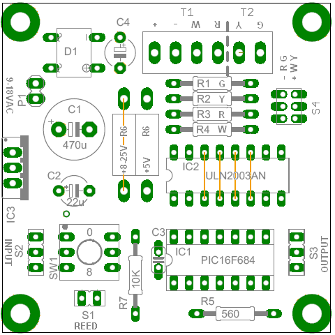 1. If your signal has LEDs wired in the COMMON CATHODE configuration or
if it has a BIDIRECTIONAL red/green LED then do NOT install the 16-pin
socket for IC2. Instead, install the four jumper wires on IC2 as shown
in the diagram. Bend the leads to hold the jumpers in place, but don't
solder them yet.
1. If your signal has LEDs wired in the COMMON CATHODE configuration or
if it has a BIDIRECTIONAL red/green LED then do NOT install the 16-pin
socket for IC2. Instead, install the four jumper wires on IC2 as shown
in the diagram. Bend the leads to hold the jumpers in place, but don't
solder them yet.
2. If instead your signal has LEDs wired in the COMMON ANODE configuration or has INCANDESCENT BLUBS then install the 16-pin (longer) socket for IC2 being certain to orient it with its notch aligned with the semicircle on the board. Bend the corner pins to hold it in place, but don't solder it yet.
3. Insert the 14-pin socket for IC1 being certain to orient it correctly with its notch aligned with the semicircle on the board.
4. Insert the four-pin bridge rectifier (D1) making sure that the + and - pins go into the correct holes.
5. Solder these installed parts. Suitable solder is provided. (Never use acid flux or acid core solder on electronic devices.) It helps to anchor the board with a clamp or weight while soldering. Examine the soldered joints to make sure the solder flowed into all the gaps, and that there are no shorts. If jumpers were installed, clip off the extra leads.
6. Insert the small 0.1 ceramic capacitor (C3 "104") and bend the leads
to hold it in place.
Insert the resistors by bending each lead 90 degrees with the tip
of your pliers:
R7 is 10k ohms (brown, black, orange, gold).
R5 (unused in the timer version) is 560 ohms (green, blue, brown, gold).
R1-R4 are the values that determine the brightness of each LED. If your
signal has resistors attached or has incandescent bulbs then use jumper
wires instead of resistors.
R6 varies depending on the type of signal (see Configurations on page
1.) For common anode signals it's usually a jumper wire installed in the
+8-25V position. For common cathode signals it's usually not installed,
the exception being Pennsy signals. For incandescent signals it's a
jumper in the +8-25V position unless the board is operated from 12 VAC,
in which case a 47 ohm 1 watt resistor is used instead to reduce the
rectified voltage back down to 12 VDC. If in doubt, ask Loren.
Double check then solder these parts, and then trim off the extra leads.
7. For a kit with the timer option, insert the blue rotary switch. It might be necessary to first flatten the kinks in the pins. Be sure to orient it correctly with the dots aligned. Solder it.
8. If not using screw terminals then solder in the miniature six-hole socket (S4).
9. Solder in the two-hole socket (not pins, S1) at the location labeled REED. Tape can be used to hold it straight while soldering.
10. For the prototypical version, solder in the INPUT socket (S2) and the OUTPUT socket (S3).
11. Solder in the two-pin power connector (P1, at 9-18 VAC). The short ends go in the board with the long ends sticking up.
12. If you're using the screw terminals, determine if you need two, four, or six positions. Note that a signal without a yellow aspect attaches its green to the W (white) terminal. (White is on when red is off.) If all six positions are used, attach a four-terminal block to a two-terminal block, by sliding them together, before inserting them into the board. Make sure the openings for attaching wires face outward toward the edge of the board, then solder.
13. Insert the (smaller) 22uF capacitor (C2, near the label TAB). Make sure it's oriented correctly. (The minus side of the capacitor is marked with a white stripe, and its lead on the other side goes into the hole in the board marked "+".) Insert the (larger) 470uF capacitor (C1, near the label SIDE) making sure it's oriented correctly. Solder and trim.
14. (Capacitor C4 is normally not needed.)
15. Insert the three-pin voltage regulator (IC3, it looks like a big transistor). Be sure to orient it with its metal tab toward the center of the board (where is says TAB SIDE). Solder and trim.
16. Don't plug any ICs into sockets until the Testing section below.
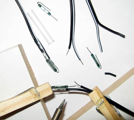 WARNING: Never bend the leads on a reed switch without supporting them
with pliers, otherwise the glass tube will very likely break. (Believe
me, I know.)
WARNING: Never bend the leads on a reed switch without supporting them
with pliers, otherwise the glass tube will very likely break. (Believe
me, I know.)
1. Peel apart about 1-1/2" of the twin wires on about a one-foot length of 24 gauge cable. Trim the wires to match the leads on the reed switch. One wire will be about 3/8" shorter than the other. (It doesn't matter which lead attaches to the wire with the white stripe.) Strip 1/4" of insulation from the wires and twist the strands together.
2. Tin the leads on the wires and on the reed switch by coating them with solder.
3. Solder the wires onto the reed switch. The tinning process makes this easier. It's often unnecessary to apply more solder.
4. Encapsulate the reed switch in a piece of 3/16" heat-shrink tubing about 1-1/4" long. Use a heat gun (lighter, match, or soldering iron) to heat the tubing until it shrinks evenly around the reed switch. The tubing should not extend above the top of the glass tube.
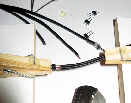 5. Attach a two-pin connector to the wires at the opposite end of the reed
switch as follows.
5. Attach a two-pin connector to the wires at the opposite end of the reed
switch as follows.
6. Strip 1/8" insulation off both leads of the twin-lead wire. Strip both leads at the same time using ordinary wire strippers. Tin the leads.
7. Align the stripped ends with a two-pin connector as shown in the photo. The short end of the connector is the solder end. Use a screwdriver to slightly spread the wire leads if needed to get a good alignment with the connector.
8. Solder the wires to the connector.
9. Apply a dab of hot glue to the gap between the wire leads to prevent them from ever shorting.
10. Make a power cable by cutting off a length of twin-lead wire and attaching one end to a two-hole connector, like was done for the reed switch cable but using a two-hole connector instead of a two-pin connector.
11. For the prototypical version, make a cable that connects the INPUT to the OUTPUT of another board. Allow enough length of twin lead wire to span between signals, plus some extra. Solder the three-pin connectors onto each end. The lead with the white stripe goes to the center pin, and the other lead goes to an outer pin (it doesn't matter which). If the inputs and outputs of the boards are not connected in a complete loop then a long reed switch cable is needed that connects to the INPUT of the last board (see figure on page 1). The two pins of the reed cable can plug into either side of the three-hole socket.
1. The order of the pins on the miniature connector is indicated on the circuit board. Signals without a yellow aspect connect green to the white (W) output. (White is on when red is off.) Soldering the pins is moderately difficult because of their small size and because the plug can easily melt.
2. Insert the plug into the socket on the board. This not only anchors it but also helps keep it from melting.
3. Twist any strands on the leads of the signal together and tin them with solder. Tin the pins on the plug, then tack the leads onto the plug. Verify that the connections are correct.
4. Remove the plug. Key it by clipping off an unused pin and inserting it into the corresponding hole in the socket.
5. Reinforce the wire connections to the plug with a dab of hot glue.
.
1. Plug the power cable into the two pins extending up from the board, and connect the other end to a power source appropriate for your signal: accessory power on a train transformer, DCC track, 9 VAC wall transformer, or any 9 to 24 volt DC source (polarity doesn't matter).
2. With a meter verify that there is 5.0 volts between pins 1 and 14 on IC1 (at the end near C3). If the voltage is wrong, do not insert the ICs until the problem is corrected.
3. Unplug the power cable.
4. Plug the ICs into their respective sockets (there is only one IC for the common cathode configuration) being sure to orient them correctly. The dimples in the ICs go next to the holes labeled "1." Make sure all the pins go into the holes.
5. Connect your signal. (A signal without a yellow lead connects its green lead to the W output--white is on when red is off.) If the signal is connected wrong, it won't damage anything (unless you connect an LED of the right polarity without a series resistor across the + and - terminals).
6. Plug the reed switch cable into the board at the label REED (S1).
7. If the rotary timer switch is installed, set it to 1. The time duration is equal to the position number times four seconds, so for this test the signal will change four seconds after being triggered. (The letter A = 10, times 4 gives 40 seconds; F = 15, times 4 gives one minute.)
8. Connect the power. The green light (aspect) should appear.
9. Use a magnet to momentarily close the reed switch. The signal should turn red.
10. If there is no rotary timer switch, such as with the prototypical version, the other aspects can be tested by connecting a reed switch to the INPUT socket, and activating it with a magnet.
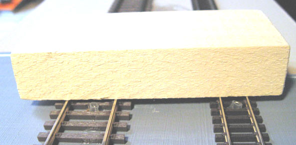 2. Attach a 1/8x1/8" super magnet, with its poles (axis) oriented up and
down, under an engine at its center near the front. (For 3-rail track
mount a pair of magnets side-by-side so the reed will activate when the
train travels in either direction.) It might not be necessary to glue
the magnet if it attaches to some metal. The magnet must pass within
1/8" of a reed switch to activate it.
2. Attach a 1/8x1/8" super magnet, with its poles (axis) oriented up and
down, under an engine at its center near the front. (For 3-rail track
mount a pair of magnets side-by-side so the reed will activate when the
train travels in either direction.) It might not be necessary to glue
the magnet if it attaches to some metal. The magnet must pass within
1/8" of a reed switch to activate it.
3. For the prototypical version, a magnet must also be attached under a caboose (or other rear-end car) at its center near the rear.
4. Magnets should clear the tops of the rails by about 1/32". If it turns out they aren't strong enough to activate the reed switch, additional magnets can be stacked onto the originals. The magnetic fields will add.
5. For timer operation, set the rotary switch for the desired time delay, which is four seconds per position. For prototypical operation if this switch is installed, it must be set to 0.
6. Mount the circuit board under the layout near the signal using the wood screws and nylon spacers provided.
7. Connect the cables for the signal, reed switch, and power. For prototypical operation, connect the INPUT to the OUTPUT of the next board down the track, as shown in the diagram on page 1. The last board connects its INPUT to a reed switch.
As with any electronic device, it's a good idea to use a surge suppressor on the 120 VAC power line.
Inputs from the rotary timer switch are read, and if it's not set on 0 then its value is multiplied by 200 to determine how many loops to execute before changing the outputs to yellow. This provides a delay of four seconds per switch position. If the switch is not installed, it reads as 0.
If the timer switch reads as 0 then prototypical operation is assumed, and the software waits for a pulse on the INPUT line before changing the outputs to yellow. This input pulse comes from the next board down the track. When this next board's reed switch is pulsed a second time, by a passing caboose, it pulses its OUTPUT line.
For prototypical operation, blocks are separated by reed switches. When a train enters a block, the magnet on the engine turns the block's signal red. When the train exits the block, the magnet on the caboose causes a second pulse on the reed switch at the end of the block. The control board for this reed switch then sends back a pulse to the preceding control board that changes its signal to yellow. When the caboose clears the second block, the third signal will be red, the second board receives a pulse that turns its signal yellow, and the first board receives a second pulse that turns its signal green.
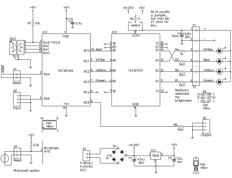
The schematic diagram shows the block signal controller with both the timer and prototypical options. Outputs are configured for a B&O signal. The PIC microcontroller is at the left, the driver transistor array is at the right, and the five volt power supply is at the bottom. A photocell can replace the reed switch on the timer version when used with a variation of the software.
-Loren Blaney